

No data
21
2025
-
08
How Does the AC Motor and Control Architecture Enable the Multi-Mode Operation and Space-Saving Design of a 94cm Tower Fan?
sales28@seemax.com.cn
Copyright Notice and Disclaimer:
All technical analyses and functional descriptions in this article belong to the author of this article, and the ultimate right of interpretation belongs to the product manufacturer. The product parameters and performance data quoted in this article are for reference only. The actual product performance may vary due to specific parameters, use of the environment, individual differences and other factors.
-
Deconstructing the 94cm Tower Fan: A Systems Overview of Airflow and Form Factor
(This introductory section breaks down the entire system into its core technological components.) -
The Core of the AC Motor: Analyzing the Electromagnetic Drive Mechanism for Torque and Reliability
(This delves into the fundamental working principle of the AC induction motor, explaining its construction and advantages for sustained operation.) -
Aerodynamic Engineering of the Vertical Air Column: Maximizing Laminar Flow in a Space-Saving Design
(This focuses on the physics and design of the fan's housing and impeller that create its characteristic tall, narrow airflow.) -
Control System Architecture: From Touch Button Interface to Motor Driver Circuitry
(This explains the electronic pathway, from the user's input on the LED touch panel to the signals that control the motor's power.) -
Algorithmic Wind Mode Implementation: The Technical Parameters of Natural, Sleep, ECO, and Normal Settings
(This subheading treats the wind modes as software-driven functions, explaining the programmed variations in fan speed and oscillation that create each distinct effect.) -
Oscillation Gearing and Kinematics: The Mechanical Translation of Rotary to Precise Articulation
(This covers the mechanical assembly—likely a worm gear reduction system—that enables the fan's smooth and automatic side-to-side movement.) -
Power Management and Efficiency: Analyzing the 45W Power Rating Across Operational Loads
(This section examines the electrical consumption and efficiency of the system, particularly under the demands of the different speed and ECO settings.) -
User Interface (UI) and Safety Protocol Integration: The Logic Behind the Timer, Child Lock, and LED Display Functions
(This focuses on the embedded programming that manages user commands, timing circuits, and safety lockout features.) -
Acoustic Performance Metrics: Evaluating Noise Emission Profiles Across Six Speed Settings
(This technical subheading addresses the sound engineering aspects, analyzing how noise is generated and managed at different operational levels.)
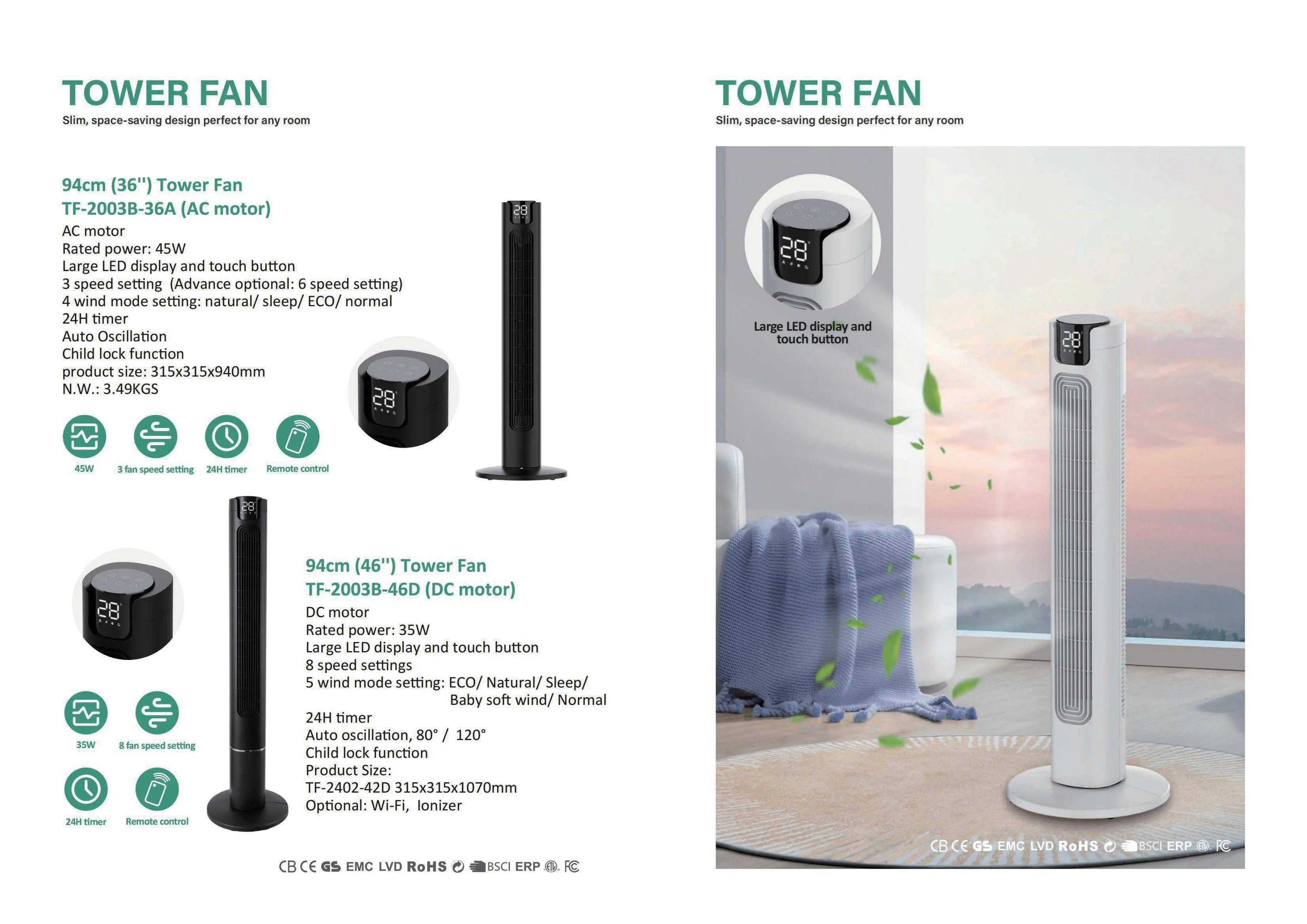
How Does the AC Motor and Control Architecture Enable the Multi-Mode Operation and Space-Saving Design of a 94cm Tower Fan?
The modern tower fan represents a significant convergence of mechanical engineering, electrical systems, and user-centric design. Moving beyond simple air circulation, devices like the 94cm TF-2003B-36A model are sophisticated appliances designed for efficiency, comfort, and integration into living spaces. This article provides a detailed technical examination of the components and principles that enable the advanced functionality of a contemporary AC motor-driven tower fan, analyzing everything from its electromagnetic core to its algorithmic user profiles. We will deconstruct its space-saving design, explore the robustness of its AC motor, and elucidate the sophisticated control architecture that manages its multi-mode operation.
1. Deconstructing the 94cm Tower Fan: A Systems Overview of Airflow and Form Factor
The fundamental appeal of a tower fan lies in its vertical architecture, a design choice with profound engineering implications. Unlike traditional axial fans (blade fans), which move air in a wide, disruptive circular pattern, a tower fan operates on a mixed-flow principle, drawing air in from the bottom and ejecting it vertically along the entire length of its column.
-
The Air Intake and Grille System: Located at the base of the unit, the intake grille is engineered with a specific open-area ratio to balance sufficient airflow with safety, preventing foreign object insertion. The geometry of the grille vanes is often angled to guide air smoothly into the fan assembly with minimal turbulent loss, which is a critical first step in optimizing overall system efficiency and reducing intake noise, a key factor in acoustic performance.
-
The Impeller and Housing Assembly: The heart of the airflow generation is a cylindrical mixed-flow impeller, housed within the vertical column. This impeller, often made from lightweight yet rigid polystyrene or polypropylene, features backward-curved aerofoil blades. These blades are designed to impart kinetic energy to the air molecules with high efficiency and lower turbulence compared to straight blades. The shroud or duct surrounding the impeller is precision-engineered to minimize air gap losses, ensuring that the maximum volume of air is accelerated through the system. This focused acceleration is what allows the 94cm tower fan to project air over a considerable distance despite its narrow space-saving design.
-
The Output Louver Mechanism: The accelerated air is forced out through a long, vertical outlet. Integrated into this outlet is a set of directional louvers. In models with auto oscillation, these louvers are connected to a gear mechanism that allows them to pivot, redirecting the column of air throughout a room. The design of these louvers directly affects the dispersion pattern, whether creating a wide, gentle breeze or a more focused stream.
2. The Core of the AC Motor: Analyzing the Electromagnetic Drive Mechanism for Torque and Reliability
The choice of an AC motor for this application is a deliberate engineering decision prioritizing longevity, consistent torque, and operational simplicity. The TF-2003B-36A utilizes a shaded-pole induction motor, a subtype of single-phase AC motor renowned for its robustness in continuous-duty applications like fan operation.
-
Electromagnetic Principles of Operation: The motor functions on the principle of a rotating magnetic field. It consists of a stator (stationary part) with laminated steel cores and copper windings, and a rotor (rotating part) which is typically a squirrel-cage design. When alternating current is applied to the main winding, it creates a pulsating magnetic field. A secondary "shading coil," a single turn of copper, is embedded around a portion of each stator pole. This coil causes the magnetic field in that portion of the pole to lag behind the field in the unshaded portion, effectively creating a phase shift. This imperfect, shifting magnetic field induces eddy currents in the rotor, causing it to rotate to "catch up" with the moving field. This simple, brushless design means there are no parts that wear out from electrical arcing, contributing to the motor's famed long-term reliability and low maintenance requirements.
-
Torque Characteristics and Speed Control: A key characteristic of induction motors is that their speed is inherently tied to the frequency of the AC power supply (e.g., 50/60 Hz). However, speed can be reduced by effectively weakening the magnetic field strength. This is achieved through a series of taps on the motor's windings. Each speed setting corresponds to a different tap, introducing more resistance or inductance into the circuit. While this reduces power and torque, it is a perfectly adequate and cost-effective method for a fan load, which is variable and requires less torque at lower speeds. The AC motor provides ample starting and running torque to overcome the initial inertia of the impeller and maintain rotation even against back pressure.
3. Aerodynamic Engineering of the Vertical Air Column: Maximizing Laminar Flow in a Space-Saving Design
The primary engineering challenge of a tower fan is to maximize the volume of air moved (measured in Cubic Feet per Minute or CFM) while minimizing its physical footprint and acoustic signature. This is a classic exercise in fluid dynamics.
-
Laminar vs. Turbulent Flow Regimes: The ideal scenario is to achieve laminar flow, where air moves in smooth, parallel layers with minimal mixing. However, due to high velocities and surface interactions, flow within the fan is inherently turbulent. The design goal is to manage this turbulence. The smooth, continuous interior surface of the fan column, free of sharp edges or obstructions, reduces friction and prevents the formation of large, energy-wasting vortices. Computational Fluid Dynamics (CFD) software is often used in the design phase to simulate and optimize the internal airflow paths, ensuring that the transition from the impeller to the outlet is as aerodynamically clean as possible.
-
The Ejector Effect and Entrainment: As the high-velocity jet of air exits the narrow outlet louvers, it creates a low-pressure zone that pulls, or "entrains," the surrounding room air along with it. This ejector effect effectively amplifies the perceived airflow beyond what the fan physically moves itself, increasing its cooling efficiency without consuming more energy. The vertical design of the 94cm tower fan capitalizes on this by creating a tall, curtain-like flow that promotes effective mixing and circulation of air throughout the entire volume of a room, from floor to ceiling, a significant advantage over shorter pedestal fans.
4. Control System Architecture: From Touch Button Interface to Motor Driver Circuitry
The user's command is merely the beginning of a complex electronic process. The control architecture is a hierarchical system that translates a simple touch into a precise electromechanical action.
-
The User Interface Layer: The large LED display and touch button panel is built on a capacitive sensing system. A microcontroller unit (MCU) constantly monitors the capacitance of specific electrodes behind the panel. A touch from a finger changes this capacitance, which the MCU detects as a valid input. This signal is debounced and processed by the MCU's firmware.
-
The Logic and Processing Layer: The MCU is the brain of the operation. It runs the embedded software that manages all functions: interpreting button presses, driving the LED display to show settings like timer or speed setting, and storing the state of features like the child lock function. Its most crucial role is executing the logic for the advanced wind mode setting (Natural, Sleep, ECO, Normal). Each mode is a pre-programmed routine that dictates how the MCU controls the motor and oscillation.
-
The Power Delivery Layer: The MCU cannot drive the motor directly. It sends a low-voltage control signal to a solid-state relay (SSR) or a triac-based circuit. This component acts as a high-speed electronic switch, modulating the power delivered from the wall outlet (120V/240V AC) to the AC motor windings. For speed control, the MCU selects which motor tap to energize by activating the corresponding relay. This entire integrated control board is what seamlessly orchestrates the fan's behavior from a user's perspective.
5. Algorithmic Wind Mode Implementation: The Technical Parameters of Natural, Sleep, ECO, and Normal Settings
The pre-programmed wind modes are the software intelligence that elevates the fan from a simple appliance to a comfort-optimizing device. Each mode is a distinct algorithm running on the MCU.
-
Normal Mode: This is the baseline operation. The MCU supplies continuous power to the motor at the user-selected speed tap (e.g., 1, 2, or 3). It provides maximum, consistent airflow.
-
Natural Mode: This algorithm mimics the stochastic, varying breeze of nature. The MCU pseudo-randomly cycles the motor between different power levels (e.g., switching between the taps for medium and high speed in an irregular pattern). This varies the airflow's velocity and force, preventing the user's body from acclimating to a constant stream, which is often perceived as more comfortable and refreshing over long periods.
-
Sleep Mode: Focused on minimizing acoustic disruption and energy use overnight, this algorithm typically starts the fan at a medium-low setting and then gradually reduces the fan speed over a period of 30 to 60 minutes until it settles at its quietest, lowest power setting. This gradual reduction coincides with the body's natural cooling process as it prepares for sleep.
-
ECO Mode: This is a closed-loop feedback system. A negative temperature coefficient (NTC) thermistor on the main PCB acts as an ambient air temperature sensor. The MCU continuously reads the resistance of this sensor (which correlates to temperature). The firmware is programmed with a target temperature or a temperature band. As the room cools down (presumably because the air conditioning has reached its set point or the evening air is cooler), the MCU will automatically step down the fan speed to reduce power consumption and prevent over-cooling. This automated energy optimization is a key feature for reducing the 45W rated power consumption even further during extended use.
6. Oscillation Gearing and Kinematics: The Mechanical Translation of Rotary to Precise Articulation
The auto oscillation feature is a elegant mechanical solution to distribute air throughout a space. It transforms the continuous rotary motion of a small dedicated motor into a smooth, slow, reciprocating motion.
-
The Gear Reduction System: A small, low-RPM synchronous AC motor or a DC gearmotor provides the initial rotation. This motor's output shaft spins at a rate that is far too fast for a graceful oscillation. It is connected to a multi-stage gear reduction system, typically made of durable engineering plastics like nylon or acetyl. Each gear mesh reduces the speed and increases the torque exponentially. A common final reduction ratio might be 360:1, meaning the output gear completes one full revolution for every 360 revolutions of the motor shaft.
-
The Crank Mechanism: The final, slow-moving gear is not connected directly to the louver assembly. Instead, it has an off-center pin that acts as a crank. This pin sits inside a connecting rod or a sliding channel on the oscillating component. As the gear rotates, the crank pin translates the rotary motion into a back-and-forth, sinusoidal reciprocating motion. This kinematic chain is designed for smooth operation, minimal play, and low noise, ensuring the 94cm tower fan can distribute air quietly and effectively up to a wide angle, often 70-90 degrees.
7. Power Management and Efficiency: Analyzing the 45W Power Rating Across Operational Loads
The rated power of 45W represents the maximum electrical power consumption under highest load (highest speed setting without oscillation). Actual consumption is dynamic and varies significantly based on operational mode.
-
Understanding the Power Rating: The 45W rating is a measure of real power (Watts), which is the capacity to do work. It is calculated as Voltage (V) x Current (A) x Power Factor (a value between 0 and 1 representing efficiency). Induction motors have a lagging power factor, meaning not all the apparent power (VA) drawn from the wall is converted into useful work (torque and airflow); some is used to energize the magnetic field. The design aims to maximize this power factor to stay efficient.
-
Power Consumption by Mode: At speed setting 1, power consumption may drop to as low as 15-20W. The ECO mode will dynamically adjust consumption between this lower bound and the 45W maximum based on ambient temperature. The sleep mode will progressively lower consumption over time. The oscillation motor adds a negligible amount, typically less than 2-3W. This variance demonstrates that the average energy use over a daily cycle is often substantially lower than the maximum rating, a crucial consideration for energy-conscious consumers.
8. User Interface (UI) and Safety Protocol Integration: The Logic Behind the Timer, Child Lock, and LED Display Functions
The firmware running on the MCU manages complex state machines to ensure features work cohesively and safely.
-
24H Timer Implementation: This is a countdown function. When set, the MCU starts an internal counter that decrements with the passage of time (tracked by its internal clock). When the counter reaches zero, the firmware executes a shutdown routine, cutting power to the motor and all other functions, returning the device to an off state. It allows for automated operation, ensuring the fan doesn't run indefinitely.
-
Child Lock Function: This is a software-based safety feature. When activated (usually by a long-press of a specific button combination), the firmware ignores all subsequent input from the touch panel except for the specific command to deactivate the lock. This prevents accidental activation or setting changes by children or pets, adding a critical layer of safety and operational security.
-
LED Display Driver: The MCU has dedicated pins connected to segments of the LED display. To show a number or icon, the firmware sends a signal to light up the specific combination of segments required to form that character, providing clear user feedback on the selected settings.
9. Acoustic Performance Metrics: Evaluating Noise Emission Profiles Across Six Speed Settings
Noise is an undesirable byproduct of operation, and its minimization is a key design goal. The acoustic profile is a combination of several factors.
-
Sources of Noise Emission: The primary sources are aerodynamic noise (air turbulence at the intake, impeller, and outlet) and mechanical noise (motor bearings, gear meshing in the oscillation assembly, and minor component vibration). At lower speeds, the dominant sound is often the smooth, broadband whoosh of moving air. At higher speeds, motor hum and higher-frequency whistles from the impeller tips may become more apparent.
-
Measurement and Design Mitigation: Sound pressure level is measured in decibels (dBA). Designers use techniques like optimizing the impeller blade angle and count to reduce tip vortices, ensuring tight tolerances and balances to minimize mechanical vibration, and using acoustic dampening materials inside the housing to absorb sound. The result is that on its lowest speed setting and in sleep mode, the fan operates at a whisper-quiet level, often below 35 dBA, making it suitable for bedrooms and offices without causing distraction.
Conclusion
The contemporary 94cm tower fan, exemplified by the TF-2003B-36A model, is a testament to the sophisticated integration of mature and modern technologies. Its space-saving design is not merely an aesthetic choice but an aerodynamic one, enabling efficient vertical airflow. The core AC motor provides a backbone of unmatched reliability and consistent torque, forming the robust heart of the system. This hardware is given intelligence through a sophisticated control architecture that translates user input into precise actions, managing everything from basic speed settings to complex, algorithm-driven wind mode operations like Natural, Sleep, and ECO. Every aspect, from the kinematic oscillation system to the power-saving protocols and acoustic damping, is meticulously engineered to deliver optimized comfort, efficiency, and integration into the modern living environment. It is a device where every component, from the electromagnetic stator to the line of code governing the timer, plays a deliberate role in a harmonious electromechanical symphony.
Frequently Asked Questions (FAQ)
Q: Is an AC motor fan better than a DC motor fan?
A: Both have advantages. AC motors, as used in this model, are typically less expensive, simpler in design, and renowned for exceptional longevity and durability due to their brushless construction. DC motors are generally more energy-efficient and offer a wider range of speed settings with finer control, often at a higher cost. The choice depends on prioritizing ultimate reliability and value (AC) versus peak efficiency and granular control (DC).
Q: The 'Natural' mode seems random. Does it actually serve a purpose?
A: Absolutely. It's not truly random but pseudo-randomly programmed. Its purpose is physiological. A constant, monotonous airflow can lead to a phenomenon where your body acclimates and no longer perceives the cooling effect. The varying pattern of the Natural mode prevents this acclimation, providing a cooling sensation that feels more intense and comfortable over extended periods, mimicking the natural environment it's named after.
Q: How does the Child Lock function work on a touch panel?
A: Unlike a mechanical lock, this is a software function. When you activate the Child Lock (usually by holding a button for 3-5 seconds), the microcontroller's firmware is programmed to enter a state where it ignores all subsequent input signals from the touch sensors. The panel is still physically active, but the "brain" of the fan is not listening. Only the specific, pre-programmed deactivation command (e.g., holding the same button again) can exit this state.
Q: My fan's oscillation has become jerky or noisy. What could be wrong?
A: This is almost certainly a mechanical issue within the oscillation gearing and kinematics. The most common cause is a failure within the gearbox—a worn gear tooth, a cracked gear, or a dislodged crank pin. Dust and debris ingress over years can also cause increased friction and wear. Due to the complexity of this assembly, repair typically requires replacing the entire gear motor unit.
Q: The ECO mode doesn't seem to change anything in my room. Why?
A: The ECO mode's effectiveness is dependent on a changing ambient temperature. If you are in a room where the temperature is constant (e.g., a well-insulated room with a stable climate control system), the sensor will not detect a change, and thus the fan speed will not adjust. It is most effective in environments with natural temperature fluctuations, such as a room cooling down in the evening.
Related News
undefined